How We Converted a Radiator Fan Shroud From Plastic to FRP Composite
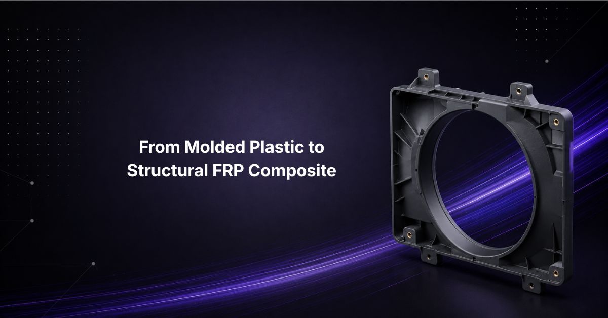
How Procurabl converted a plastic radiator fan shroud to FRP composite for a Tier-1 supplier in the UK's heavy equipment industry solving thickness, bowing, and insert integrity in hand lay-up manufacturing.
Industry: Heavy Equipment / Off-Highway
Product: FRP (fiberglass-reinforced polymer) radiator fan shroud, hand lay-up process
Why Procurabl
Customer Challenge: Convert an existing plastic radiator fan shroud - a geometrically sensitive, structurally critical component, into an FRP composite equivalent, while holding dimensional accuracy, mounting geometry, and structural integrity to the original design's requirements.
Capabilities Leveraged: FRP hand lay-up process development, laminate thickness control, insert-area reinforcement engineering, dimensional and CMM validation, temperature-performance material selection.
Result: 20 validated FRP fan shrouds delivered, with the original 3–6 mm thickness variation controlled, post-installation out-bowing resolved, insert-area chipping eliminated, and CMM-inspected dimensional conformance confirmed before dispatch.
Introduction
A radiator fan shroud isn't a cosmetic panel. It surrounds the fan itself and has to hold its geometry, mounting accuracy, and structural integrity through installation and continuous operation. When this Tier-1 supplier needed a lighter alternative to their existing plastic shroud, the brief wasn't just "make it lighter." It was: build a large, geometrically sensitive component in FRP composite that performs at least as well as the part it replaces.
The Challenge
Four problems typically determine whether a large hand-laid FRP part actually works, and this project ran into all four:
Uneven thickness. Initial builds showed thickness variation of roughly 3–6 mm enough to affect weight, dimensional stability, surface consistency, local stiffness, and repeatability part to part.
Out-bowing after installation. The shroud tended to bow outward once mounted, meaning dimensional accuracy couldn't be judged in the moulded state alone: flatness, mounting pitch, and post-cure stability all had to hold once the part was actually installed.
Chipping around inserts. With multiple mounting inserts in the component, chipping appeared at the insert interfaces, a laminate-reinforcement problem, not a materials problem.
Dimensional inspection requirements. The customer required CMM inspection of two randomly selected parts, with inspection reports delivered before dispatch, making dimensional validation a hard gate, not a formality.
The Solution
We developed the shroud as an FRP composite component using the hand lay-up process, with the development approach built specifically around the four problems above:
- Controlled laminate thickness: build-up managed to eliminate local resin or fibre accumulation, directly addressing the 3–6 mm variation
- Insert-area reinforcement: the laminate-to-insert interface engineered specifically to reduce chipping and hold surrounding thickness relative to the insert head
- Flatness and mounting control: overall flatness, mounting pitch, insert position, and post-installation behaviour all treated as controlled characteristics, not just moulded-state geometry
- B-side surface finish: the specified finished surface requirement built into the manufacturing process from the start, not addressed as a post-process fix
Engineering and Process Development
This was run as an NPI/development program, not a part-manufacturing exercise:
Existing Plastic Component → Pattern/Tool Development → FRP Laminate Development → Hand Lay-Up Manufacturing → Thickness & Insert Control → Dimensional Validation → CMM Inspection → Part Delivery
Material selection had to account for the customer's stated operating requirement of approximately 100–130°C continuous exposure, including ambient environmental effects, which meant selecting the resin and fiberglass system against that temperature-performance criteria, with technical data sheets provided for customer approval.
Quality and Validation
Dimensional quality was a first-class project requirement, not a final check:
- Thickness control
- Insert-area dimensional control
- Flatness and mounting-pitch control
- Visual inspection of insert areas
- CMM inspection of randomly selected parts, with reports delivered before dispatch
The Result
20 FRP radiator fan shrouds delivered, converting an existing plastic construction to a validated fiberglass-reinforced composite solution:
- Thickness variation resolved through controlled laminate build-up
- Out-bowing resolved through improved dimensional and mounting control
- Insert-area chipping resolved through local reinforcement and insert integration
- Flatness and mounting pitch held as controlled characteristics throughout
- CMM inspection built into the customer validation process, not bolted on after
- B-side surface-finish requirement met as specified
Beyond the material conversion itself, the project required solving the specific issues that typically determine whether a large hand-laid composite part succeeds: thickness consistency, dimensional stability, mounting accuracy, insert integrity, and surface quality - together, not in isolation.
Need a plastic-to-composite conversion done right the first time? Let’s talk
FAQ
How do you convert a plastic component to FRP composite without losing dimensional accuracy?
The key is controlling laminate thickness build-up during hand lay-up so resin and fibre don't accumulate unevenly across the part, combined with validating geometry in the installed state, not just the moulded state, components can meet spec straight out of the mould and still bow or shift once mounted. Dimensional inspection (CMM on parts) should be built into the process as a gate, not a final check.
What causes thickness variation and out-bowing in hand lay-up FRP parts, and how is it controlled?
Thickness variation typically comes from inconsistent resin/fibre distribution during layup; out-bowing after installation usually reflects laminate stresses or geometry that wasn't validated under actual mounting conditions. Both are addressed through controlled laminate build-up during manufacturing and dimensional validation that specifically checks flatness and mounting pitch post-installation, not just as-moulded.
What temperature range can FRP composite components withstand in engine or radiator-adjacent applications?
It depends on the resin and fiberglass system selected, for this application, the component needed to withstand roughly 100–130°C continuous exposure including environmental effects, which requires selecting a resin/glass-fibre system against that specific temperature-performance criteria and validating it against technical data sheets, rather than assuming a standard FRP layup will hold.
What quality validation is required for FRP composite parts supplied to OEM heavy equipment manufacturers?
Typical requirements include thickness and insert-area dimensional control, flatness and mounting-pitch validation, visual inspection of critical areas like insert interfaces, and CMM inspection of parts with reports provided before dispatch treating dimensional quality as a core project requirement throughout development, not a final inspection step.